Iron foundry basics
Practical Action
Although the induced draught furnace is a well-proven method of melting cast iron, it is very
dependent on weather conditions, and the control of melting cannot be entirely accurate. The forced
draught system shown in Fig. 2 is preferable, because it allows for much more accurate control of
temperature. If electric power is not available, a centrifugal fan, manually operated, can provide
sufficient blast for melting.
It is normal to build the furnace below ground level, and to provide a trench access for removal of
ash. This arrangement has the dual advantage of a) supporting the refractory bricks, thus avoiding
the need for a complicated structure, and b) providing the operator with a working platform at
ground level - this reduces the physical effort required to lift the crucible.
The crucible "A" made of clay graphites (salamander pots) is 180 m/m outside diameter and 360
m/m high. It sits on a stool, "8" (130 m/m high), which can be made from a used crucible. The
stool is supported by fire-bars, "C", which are placed about 300 m/m from the bottom of the ash
pit. These fire-bars are originally made of steel round bar, purchased from a local steel merchant,
but when they
need replacement, they can be cast in the foundry (cast iron bars are actually more durable).
The sliding cover, "8" can be of local refractory stone. This cover should be in the closed position
when the melting is in operation. The walls of the furnace, "F", are of refractory brick. The quality of
bricks is directly related to their life. The furnace is of square construction, to the dimensions
shown, the thickness of the walls being 230 m/m. Two spaces are left, one at the bottom of one
wall for induced draught and for the clearance of ashes, and the other at the top of the same wall,
for the chimney ("L") outlet. A
damper is inserted in the bottom space to regulate air flow or draught.
Description of Operation
Wood shavings, together with some charcoal, are placed on the fire-bars around the stool and fired,
before the crucible is placed on the stool by the tongs, "J". This is important because if the bottom
of the crucible is cold when it is placed on the stool, the iron may not melt properly. After placing
the crucible in position, a full charge of charcoal is added.
The crucible is now ready to receive a charge of pig and scrap iron. It is recommended, however,
that an extension or "prolong" "N" be fitted to the top of the crucible before loading. This not only
helps to support the pieces of pig iron; it also helps to keep the heat in the crucible, and thus
assist the melting process. This prolong can conveniently be made by knocking out, or cutting, the
bottom of an old crucible, so that it fits neatly into the top of the crucible proper.
Method of Loading
It is not necessary to break the pig iron into small pieces, because suitable lengths can be loaded
in a vertical position, providing the top ends do not project beyond the top edge of the prolong
(extension).
Iron recovered from scrapped machinery should be broken into small pieces, and packed closely
round the large pieces
of pig. Pig and scrap
iron must be carefully
loaded to avoid
damage to the
crucible. Some loading
could be done before
the crucible is loaded
into the furnace.
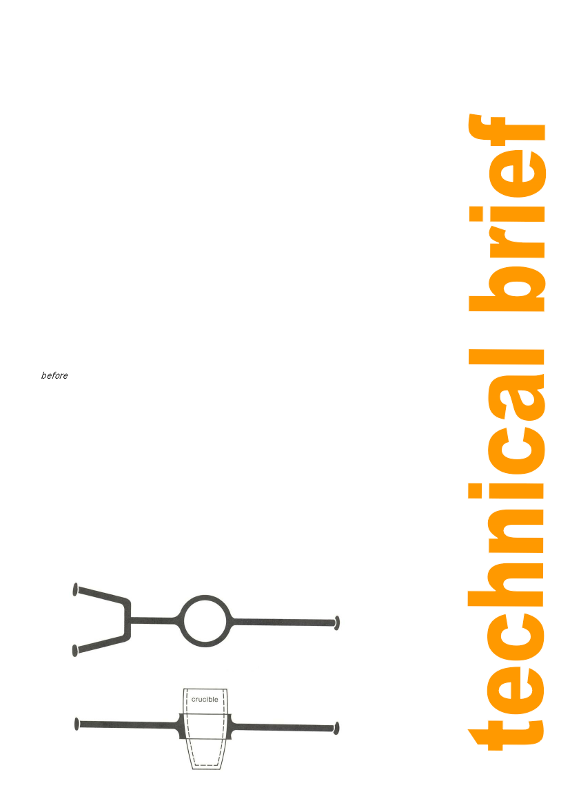
Figure 3: Carrier for
crucible (for pouring)
4